
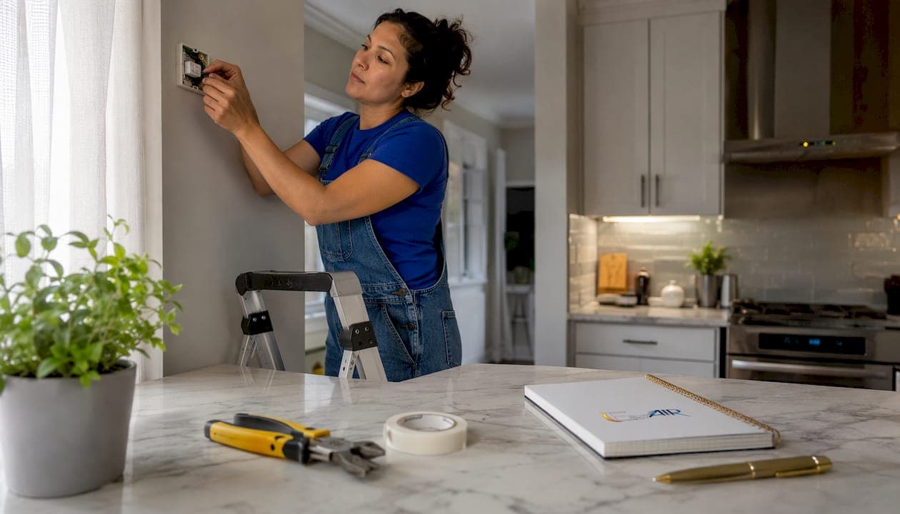
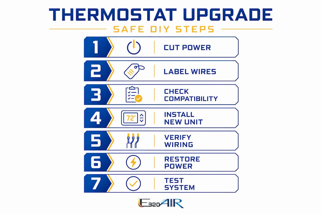
Upgrading a thermostat safely comes down to four non-negotiables: cut power at the breaker, photograph every wire before touching anything, confirm compatibility before you buy, and verify each connection against the terminal diagram before restoring power. A standard low-voltage replacement typically takes 30–60 minutes with basic household tools and requires no special license in the U.S. Get those four steps right, and the job is genuinely manageable for most homeowners.
Here is what the process looks like in practice:
- Identify your thermostat type (low-voltage 24V vs. line-voltage 120/240V) before purchasing anything.
- Turn off HVAC power at the circuit breaker and confirm it is off with a non-contact voltage tester.
- Photograph all existing wiring from close range before disconnecting a single wire.
- Label each wire with masking tape flags marked with the terminal letter (R, W, Y, G, C).
- Follow the new thermostat's terminal diagram exactly when reconnecting wires.
- Test heating, cooling, and fan functions before calling the job done.
Pro Tip: Before restoring power, hold your wiring photo next to the new thermostat's terminal diagram and compare them connection by connection. One transposed wire can cause the furnace and compressor to run at the same time, which puts serious stress on both systems.
Table of Contents
- What to consider before starting your thermostat upgrade
- Safety precautions: electrical hazards and old thermostats
- Step-by-step guide to removing the old thermostat and installing the new one
- Tips for proper thermostat mounting and placement
- Common challenges and troubleshooting tips during thermostat upgrades
- When should you hire a professional HVAC technician?
- DIY vs. professional installation: which one fits your situation?
- Expert insight on wiring verification and avoiding HVAC damage
- E320air handles the jobs that go beyond DIY
- Key Takeaways
What to consider before starting your thermostat upgrade
The single biggest mistake homeowners make is buying a new thermostat before checking whether it works with their system. Compatibility is not guaranteed, and an incompatible unit can cause short cycling, system lockouts, or compressor damage.
Know your system type first. Most homes use a low-voltage (24V) forced-air system with a gas furnace, central air conditioner, or heat pump. A smaller number use line-voltage systems, typically electric baseboard heaters, which run on 120V or 240V. These two system types are not interchangeable, and the thermostat you need differs completely between them.
Check your wire count. Pull off your current thermostat's faceplate and count the wires. If you have only two or three wires, your options for a smart thermostat are limited. Most smart thermostats require at least four wires, and many need five, including a C-wire for continuous 24V power. Older homes often lack a C-wire because older mechanical thermostats did not need one. A C-wire adapter kit, which is generally affordable and available from multiple suppliers, solves this without running new cable.
Use the manufacturer's compatibility checker. Every major thermostat brand offers a free online tool. You enter your wire labels, and it confirms whether the new unit works with your system. Run this before purchasing. Honeywell Home, for example, provides a compatibility checker that walks you through your current wiring configuration step by step.
Gather your tools before starting. You will need a flathead and Phillips screwdriver, masking tape, a marker, a non-contact voltage tester, a level, and possibly a drill with wall anchors. Having everything within reach keeps the job under an hour.
Know your local code requirements. Some jurisdictions require a permit for thermostat replacement, particularly for line-voltage systems. Check with your local building department if you are unsure.
Safety precautions: electrical hazards and old thermostats
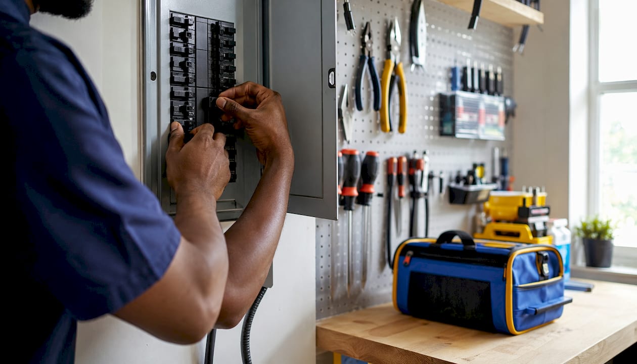
The most important safety step is also the simplest: turn off the power at the circuit breaker before touching any wires. Do not rely on the thermostat's off switch. The breaker is the only way to cut power to the wiring at the wall.
Understand what you are dealing with electrically. Low-voltage thermostats use thin 18-gauge wires and operate on safe 24V circuits. High-voltage thermostats use thick 12-gauge or 14-gauge wires and carry 120V or 240V, which can cause serious injury. If your wires are thick or your current thermostat is labeled 120V or 240V, stop immediately and call a licensed electrician.
- Always verify power is off with a non-contact voltage tester, not just by feel or assumption.
- Work in a well-lit, dry area. Moisture and electrical work do not mix.
- Wear safety glasses when drilling into walls for new mounting hardware.
- Never work on a line-voltage system yourself. The shock risk is real and the job requires a licensed electrician.
Handle old thermostats with care. Older mechanical thermostats with glass tubes may contain mercury, a hazardous material. Do not throw them in the trash. Check with your local recycling program or hazardous waste facility for proper disposal instructions.
Lowe's advises extreme caution when removing older thermostats that may contain mercury. Improper handling risks both personal health and environmental harm. Always check with your local recycling company for disposal instructions before discarding an old unit.
A Certified HVAC Technician's most consistent advice on thermostat work: the greatest risk is not electrical shock from low-voltage wiring. It is equipment damage from incorrect connections. Treat the wiring step with the same care you would give any high-stakes task.
For a broader look at HVAC safety preparation, reviewing a comprehensive DIY maintenance checklist before you start is time well spent.
Step-by-step guide to removing the old thermostat and installing the new one
A safe installation follows a fixed sequence. Skipping steps or reordering them is where most DIY errors originate.
Step 1: Cut power at the breaker. Locate the circuit breaker controlling your HVAC system. Many homes have separate breakers for heating and cooling. Turn both off. Confirm power is off by adjusting the thermostat temperature and listening for any system response. Then verify with a voltage tester at the thermostat wires.
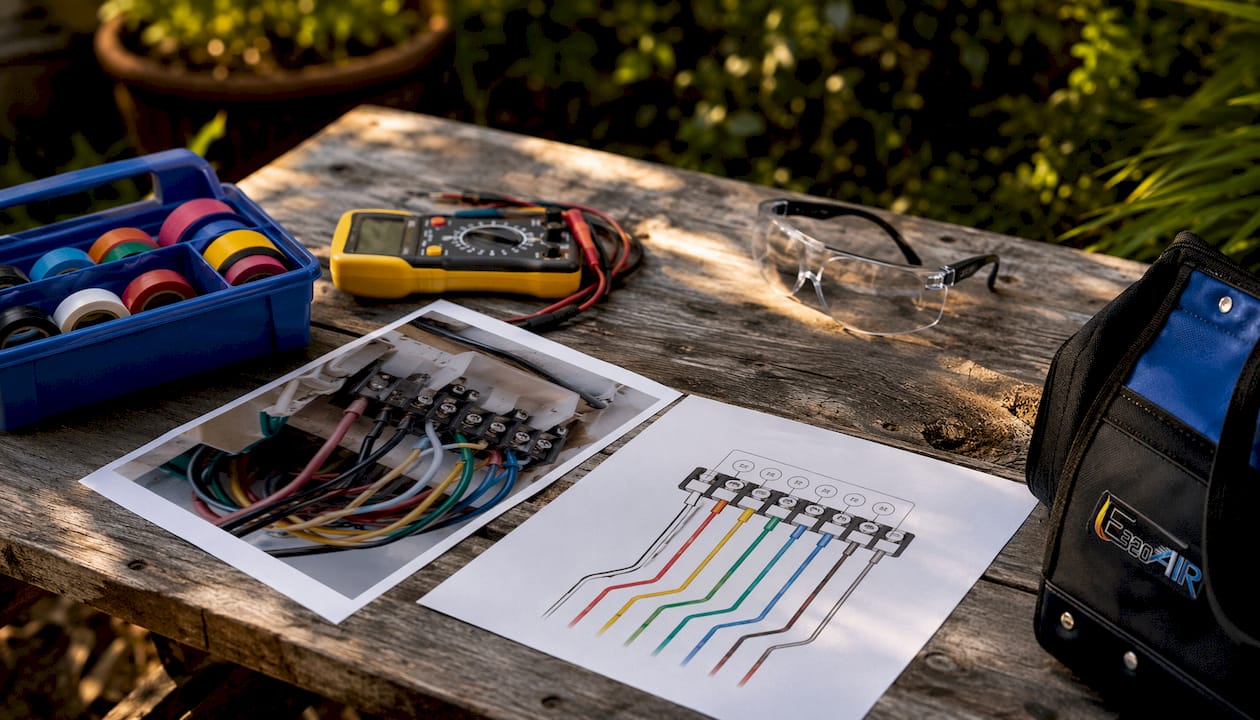
Step 2: Remove the faceplate and photograph the wiring. Most faceplates snap off or unscrew. Once removed, take two photos: one close-up showing each wire and its terminal label clearly, and one wider shot showing the full layout. These photos are your insurance policy for the rest of the job.
Step 3: Label every wire.
- Tear small strips of masking tape.
- Wrap one strip around each wire as a flag.
- Write the terminal letter on the tape (R, W, Y, G, C, O/B, etc.).
- Note any jumper wires between terminals, especially between Rh and Rc.
Step 4: Disconnect wires and remove the old base plate.
- Loosen each terminal screw or press the release tab and pull the wire free.
- Wrap the wires around a pencil laid across the wall opening so they do not fall into the wall cavity.
- Remove the mounting screws holding the old base plate and set it aside.
Step 5: Mount the new base plate.
- Feed the labeled wires through the wire opening in the new base plate.
- Hold the plate against the wall and use a level to confirm it is straight.
- Mark screw hole locations with a pencil.
- If existing holes align, use them. If not, drill new holes and insert wall anchors.
- Secure the base plate with mounting screws. Snug is enough; do not overtighten into drywall.
Step 6: Connect the wires to the new thermostat.
- Strip wire ends to expose about 1/4 inch of copper if the ends are oxidized or too short.
- Match each labeled wire to the corresponding terminal on the new base plate (R to R, W to W, Y to Y, G to G, C to C).
- For screw terminals, tighten until the wire is secure with no exposed copper touching adjacent terminals.
- For push-in connectors, insert the wire until it clicks and the connector button stays down.
- Cross-check every connection against your photo and tape labels before proceeding.
Step 7: Attach the faceplate and restore power. Snap or screw the new thermostat display onto the base plate. Restore power at the breaker. The display should power on immediately.
Step 8: Test all functions systematically.
- Cooling test: Set the temperature 5 degrees below room temperature. Cold air should reach the supply registers within 1–5 minutes.
- Heating test: Set the temperature 5 degrees above room temperature. Confirm warm air at the registers.
- Fan-only test: Switch to fan mode. The blower should run without heating or cooling engaging.
If the system does not respond correctly, cut power at the breaker and recheck your wiring against the photo. The most common errors are swapped Y and G wires and missing jumper wires between Rh and Rc.
Pro Tip: Never let two bare wire ends touch while the power is on. An accidental short between the R and C wires can blow the HVAC transformer fuse, which costs $20–$50 to replace but can take hours to diagnose and fix.
Tips for proper thermostat mounting and placement
Where you mount the thermostat matters almost as much as how you wire it. Incorrect placement near sunlight, drafts, or vents causes the sensor to read inaccurate temperatures, which forces your HVAC system to run more than it should.
- Mount at eye level on an interior wall, roughly 52–60 inches from the floor.
- Avoid exterior walls, which experience more temperature fluctuation than interior ones.
- Keep the thermostat away from windows, doors, skylights, and direct sunlight.
- Do not place it near supply vents, which blow conditioned air directly onto the sensor.
- Avoid kitchens, hallways with poor airflow, and any location near heat-generating appliances.
- Use a level during mounting. A crooked base plate is not just cosmetic; some thermostats use internal leveling sensors.
- For smart thermostats with remote sensors, follow the manufacturer's placement guide for each sensor location.
The QuietWarmth floor warming thermostat is a good example of why placement specifics matter. It is designed for radiant floor systems and requires mounting away from the floor itself to avoid false readings from the heat source it controls. Every thermostat type has its own placement logic, and the manual is the authoritative source for that specific unit.
Common challenges and troubleshooting tips during thermostat upgrades
Most installation problems trace back to one of a handful of recurring issues. Knowing what to look for saves a lot of time.
No C-wire on older systems. This is the most common obstacle when upgrading to a smart thermostat. If your current thermostat has only two or three wires, you will need either a C-wire adapter kit or a thermostat model that can operate without one. Not all "no-C-wire" workarounds are equal; some cause compatibility issues with certain HVAC systems, so check the manufacturer's documentation for your specific model.
Mislabeled or mixed-up wires. If you skipped the labeling step or the tape fell off, do not guess. Go back to your wiring photo and re-identify each wire by color and position before connecting anything.
Rh and Rc terminal confusion. Many older thermostats have a jumper wire connecting the Rh and Rc terminals. If your new thermostat has a single R terminal, connect the red wire there. If it has separate Rh and Rc terminals, install the included jumper or consult the manual. Getting this wrong usually results in either heating or cooling not working at all.
Fan running continuously. This almost always means the G wire is incorrectly connected, or a short is holding the fan relay open. Power off and recheck the G terminal connection.
System not responding at all after installation. Check the HVAC control board for a blown fuse before assuming a wiring error. A short during installation can trip the fuse without any visible sign at the thermostat. Fuse replacement is straightforward, but the wiring error that caused it must be corrected first.
If you cannot resolve the issue within 30 minutes of systematic rechecking, turn the system off and call a licensed HVAC technician. Running a system with incorrect wiring risks damaging the control board or the compressor, both of which are expensive repairs.
When should you hire a professional HVAC technician?
DIY thermostat replacement works well for straightforward low-voltage swaps. Several situations call for a professional instead.
- Heat pumps and multi-stage systems. These require specific wiring configurations, including O/B reversing valve wires, that are easy to get wrong without hands-on HVAC experience.
- Line-voltage systems. Any system with thick 12-gauge or 14-gauge wires running 120V or 240V requires a licensed electrician. Full stop.
- Unidentifiable wiring. If you cannot match your existing wires to standard terminal labels, do not guess. A professional can trace the wiring back to the control board and identify it correctly.
- No C-wire and no clear adapter path. Some older systems need a new wire run from the HVAC control board to the thermostat location. That is a job for someone with the right tools and experience.
- Repeated DIY failures. If the system still does not work correctly after two careful attempts, continuing risks compressor or control board damage.
Carrier's professional guidelines are direct on this point: complex HVAC configurations require professional expertise to optimize system function and avoid costly faults. Professional installation also preserves equipment warranties and confirms code compliance, which matters if you ever sell the home.
For a deeper look at common wiring mistakes that cause HVAC damage, reviewing real-world installation errors is useful preparation before deciding whether to proceed yourself.
DIY vs. professional installation: which one fits your situation?
| DIY Installation | Professional Installation | |
|---|---|---|
| Best for | Simple low-voltage swap, matching wire count, comfortable with tools | Heat pumps, multi-stage systems, line-voltage, unclear wiring |
| Cost | Cost of thermostat only | Thermostat plus labor |
| Time | 30–60 minutes for a standard swap | 1–2 hours including diagnostics |
| Risk | Wiring errors, blown fuse, equipment damage if steps are skipped | Minimal; professional carries liability |
| Warranty | May be voided if wiring errors damage equipment | Preserved; work is guaranteed |
| Learning value | High; you understand your system better afterward | Low; technician handles everything |
The honest answer is that most homeowners with a standard forced-air system, four or more labeled wires, and a compatible replacement thermostat can handle this themselves. The Honeywell Home thermostat lineup, for instance, is designed with DIY installation in mind, with clear terminal labeling and step-by-step app guidance. If any of those conditions are missing, the professional route protects both your equipment and your budget.
Expert insight on wiring verification and avoiding HVAC damage
The wiring verification step is where most serious installation errors happen, and the consequences are not trivial.
Certified HVAC Technician Daniel Torres, EPA 608 Universal and NATE certified with 14-plus years of field experience, puts it plainly: the greatest risk during thermostat installation is not electrical shock from low-voltage wiring. It is equipment damage. Incorrect wiring can cause the furnace and cooling compressor to run simultaneously, putting extreme stress on both systems and leading to repairs that dwarf the cost of the thermostat itself.
The verification process Torres recommends is methodical. Before restoring power, lay your wiring photo next to the new thermostat's terminal diagram and go connection by connection. Do not rely on memory or wire color alone; colors are not standardized across all HVAC systems, and a previous installer may have used whatever was available. The tape labels you applied at the start of the job are the only reliable reference.
Pay particular attention to the R and C wires. These two carry the 24V circuit, and if their bare ends touch during installation, the HVAC transformer fuse blows. The fuse itself is inexpensive, but diagnosing why the system will not power on after installation takes time and patience. Prevention is straightforward: keep bare wire ends separated until each one is seated in its terminal.
Pro Tip: After connecting all wires and before snapping on the faceplate, do a final visual scan. No bare copper should be visible outside a terminal, and no two wires should be close enough to touch. This 30-second check prevents the most common and costly installation errors.
For more on protecting your system during thermostat work, the E320air guide on thermostat calibration covers what to do after installation to confirm your system is reading and responding accurately.
E320air handles the jobs that go beyond DIY
When the wiring does not match the guide, the system is a heat pump, or a previous DIY attempt left the HVAC behaving strangely, that is exactly the situation E320air was built for. E320air is a full-service HVAC contractor handling thermostat upgrades, system installations, repairs, and maintenance across residential and commercial properties.

The difference between calling E320air and attempting a second DIY round is straightforward: a certified technician arrives with the diagnostic tools to trace wiring back to the control board, identify compatibility issues before they become equipment failures, and complete the installation with warranty compliance intact. No guesswork, no risk of a blown control board, and no second trip to the hardware store for a fuse.
If your system involves a heat pump, multi-stage equipment, or wiring that does not match any standard diagram, schedule a professional installation with E320air. For homeowners who simply want the job done right the first time, E320air's full service catalog is the place to start.
Key Takeaways
Upgrading a thermostat safely requires cutting power at the breaker, photographing and labeling every wire, confirming compatibility before purchasing, and verifying all connections against the terminal diagram before restoring power.
| Point | Details |
|---|---|
| Power off first, always | Cut power at the circuit breaker and confirm with a voltage tester before touching any wires. |
| Photo and label every wire | Take close-up photos and apply masking tape labels before disconnecting anything; these are your only reliable reference. |
| C-wire is often missing | Older homes frequently lack a C-wire; a C-wire adapter kit that resolves this for most smart thermostat installations. |
| Line-voltage means stop | Thick 12-gauge or 14-gauge wires indicate a 120V or 240V system; call a licensed electrician and do not proceed with DIY. |
| E320air for complex installs | Heat pumps, multi-stage systems, and unclear wiring call for E320air's certified technicians to protect your equipment and warranty. |